
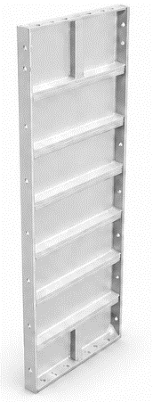
Wall panel
The main vertical member forming the wall during concrete placement.
W100–600 × H2400·2450+
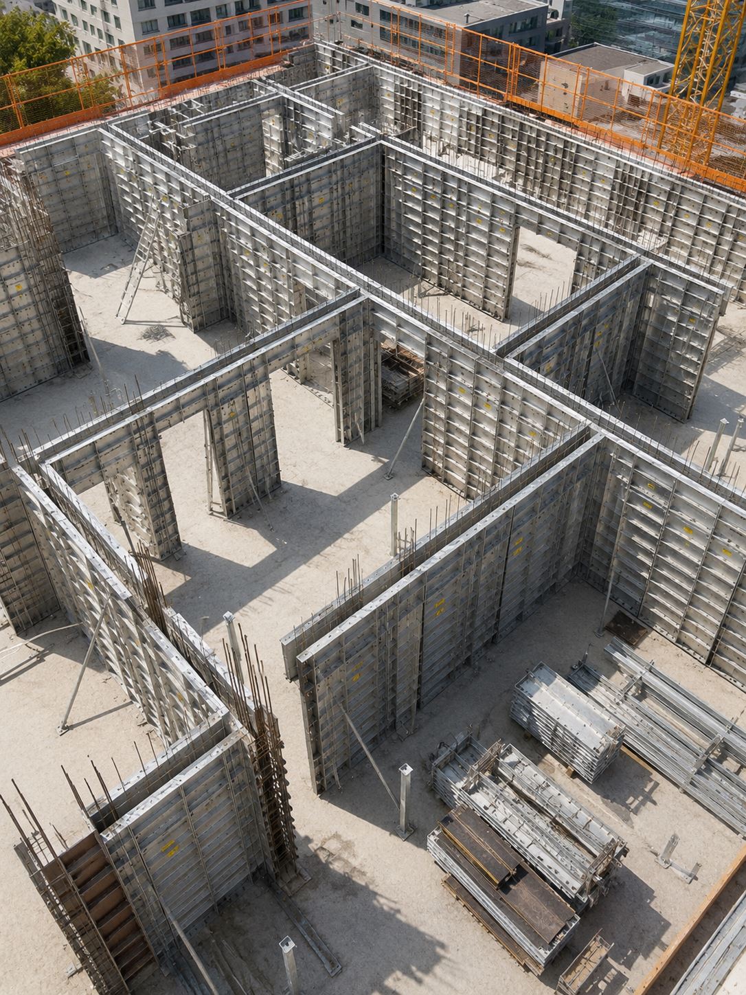
Formwork must withstand lateral pressure and structural loads floor after floor. AL-Form casts walls, slabs, beams, columns and stairs in a single cycle — lighter and stronger than Euroform. Compare with Euroform.
A 6-day cycle per floor, fair-faced concrete and a crane-free site. AL-Form moves the whole programme forward.
See the floor cycle20–60 storey towers with a repeating typical floor.
Core walls, podium and transfer levels in one cycle.
Row housing and villas — one unit in a single day.
Repeating room modules — one panel set per floor.
Standard wall panels are completed with end panels, in-corners and beam members. Every joint is fixed with round pins and wedges — no special tools required.
The main vertical member forming the wall during concrete placement.
W100–600 × H2400·2450+
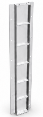
Closes the ends of parallel wall panels at wall terminations for a watertight wall.
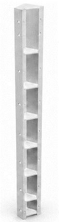
Joins two wall panels where their faces meet at internal corners.
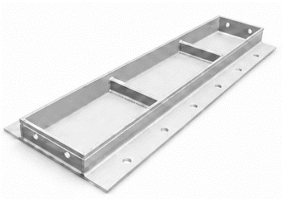
Connects the wall panel and the WEP.
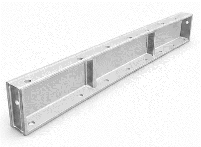
Forms the top or bottom face during the pour and resists lateral pressure.
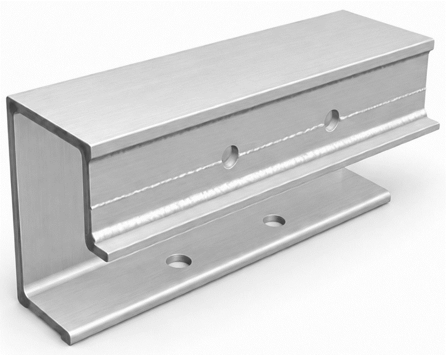
Connects with the WEP, beam panel or wall panel to form door and window openings.
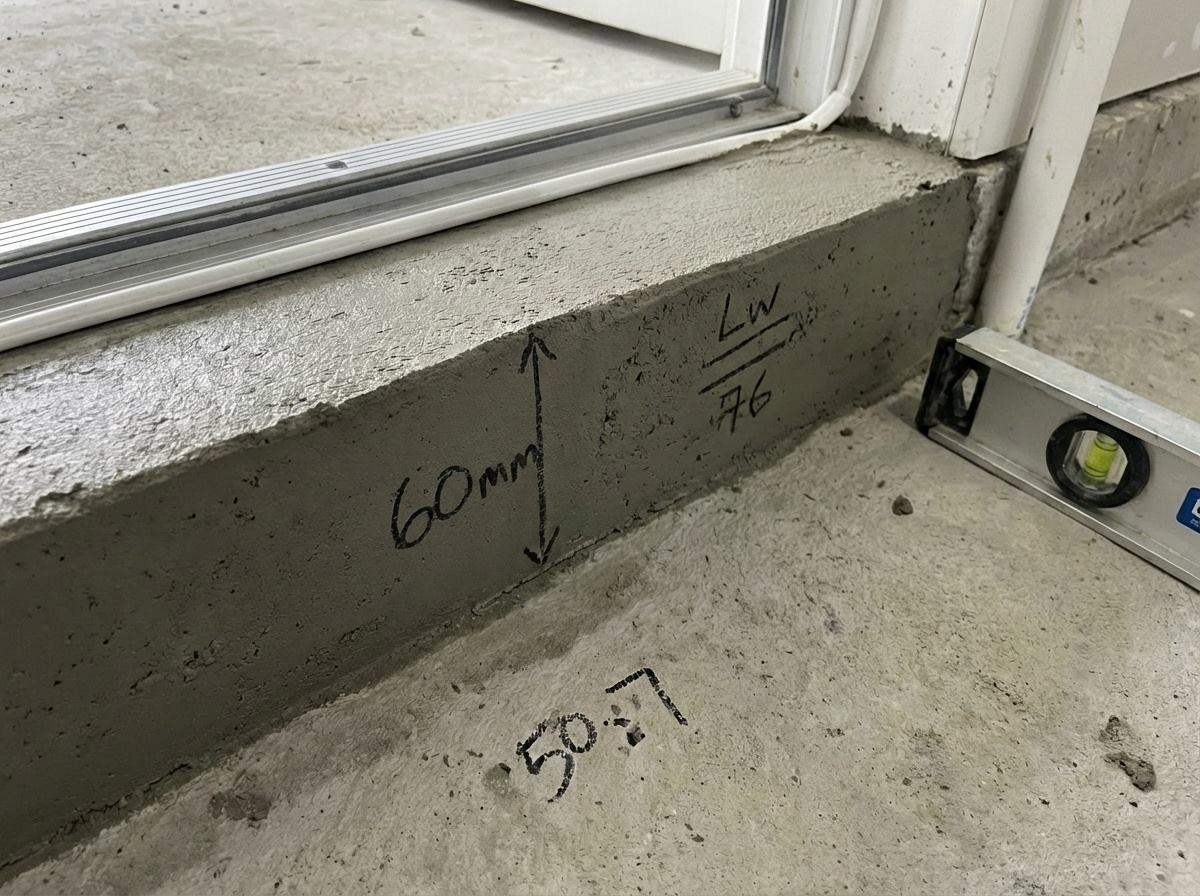
A 50 mm rocker profile at the panel base provides floor-level adjustment in 5 mm steps — precise levelling.
Slab panels rest on a grid of end beams, middle beams and prop heads, and connect to the walls through soffit members.
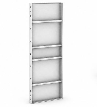
Supports the concrete load and forms the slab face during horizontal pours.
D100–600 × 1200 · D100–600 × 900
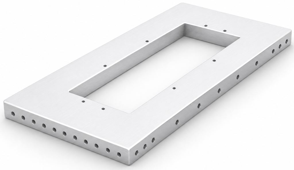
An opening that acts as the route for lifting struck panels to the next floor.
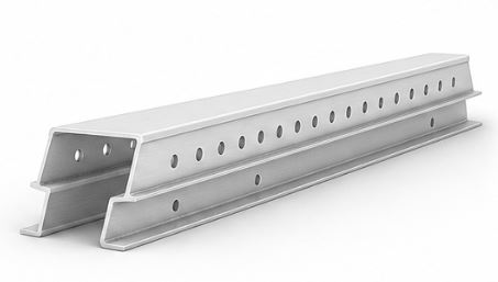
Spans between two prop heads and carries the load while the slab is formed.
MB 900·1050 × 150 · EB 300·600·750·900 × 150
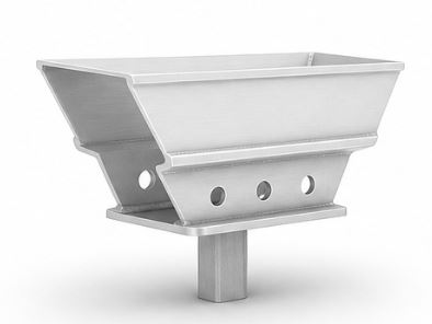
The main load node between middle beams, or middle and end beams — supports beams and props.
PH 300 × 150
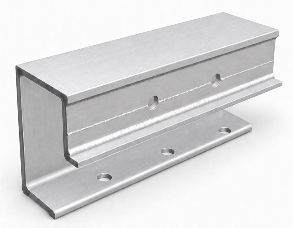
Connects wall panels and slab panels.
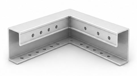
Joins wall and slab panels at corners — in-corner and out-corner types cover both directions.
Only the deck panels are struck; the beam supports stay in place. The curing slab remains supported while panels go straight up to the next floor — one set builds the whole block.
The small parts that hold the system together and create its speed — panel connection, plumb control, pressure resistance.
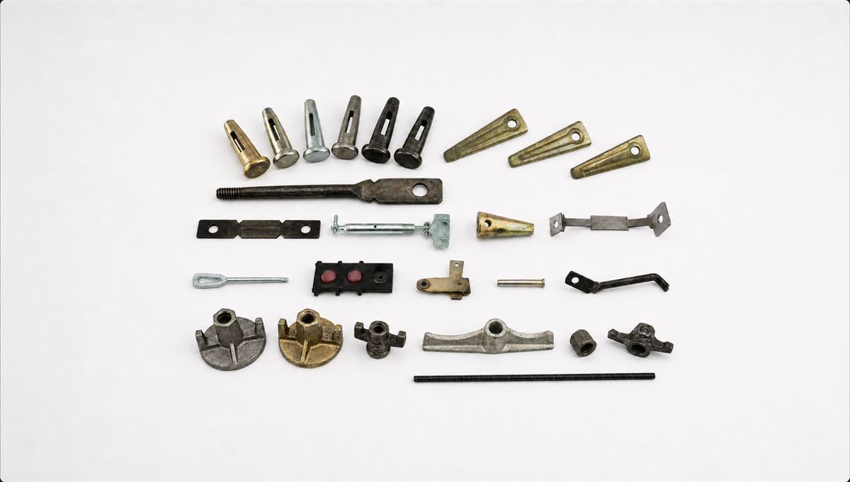
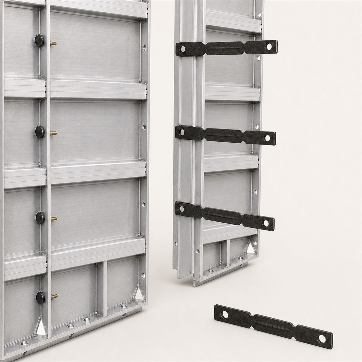
| Component | Function |
|---|---|
| Round pin | The basic part connecting panel to panel. |
| Wedge pin | Locks the round pin — fixed with a hammer, released with a hammer. |
| Flat tie | Sets the wall thickness and holds the form against lateral pressure. |
| PVC sleeve | Forms the tie hole through the wall — reusable. |
| Joint bar | Connects prop heads with middle/end beams — the structural node of the slab grid. |
| Wall · slab · lift brackets | Support working platforms and temporary walkways. |
| Long pin & wedge | Passes through the joint-bar hole to lock the middle beam and prop head. |
| Hook | Holds the alignment bar at the panel base — resists pressure and prevents leakage. |
| Kicker bolt · nut · washer | Cast-in anchors fixing brackets and kickers to the concrete face. |
| Turnbuckle alignment bar | Fine-tunes wall plumb — holds tolerance during the pour. |
High-wear parts ship with 10–20% spare quantity — so a single pin never stops a site.
Buildings are not always rectangular — neither is our formwork.
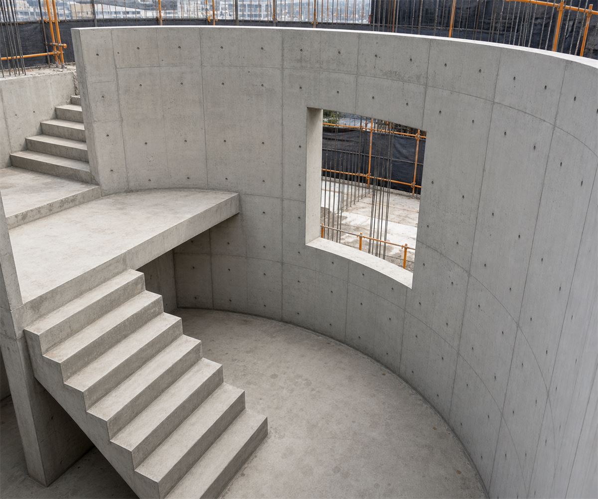
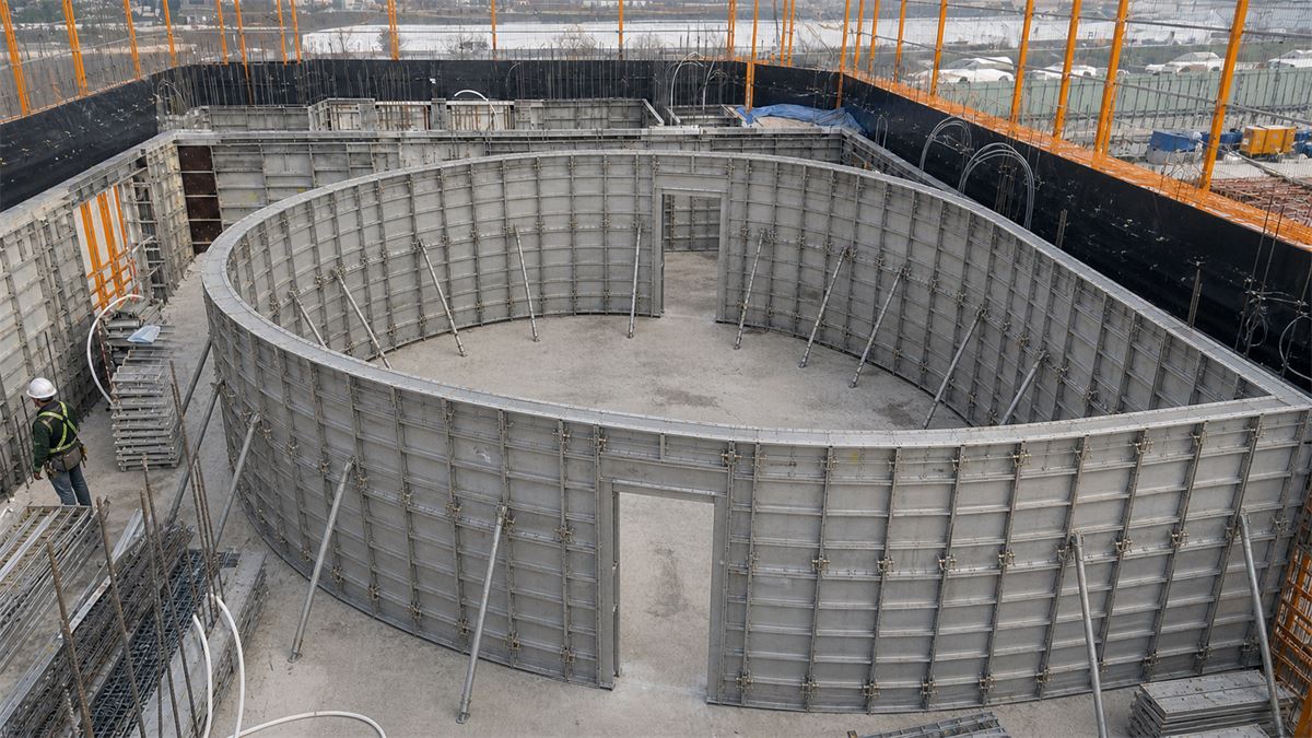
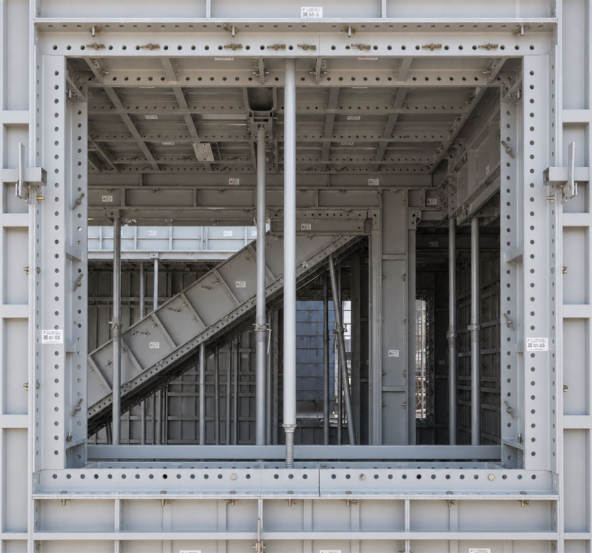
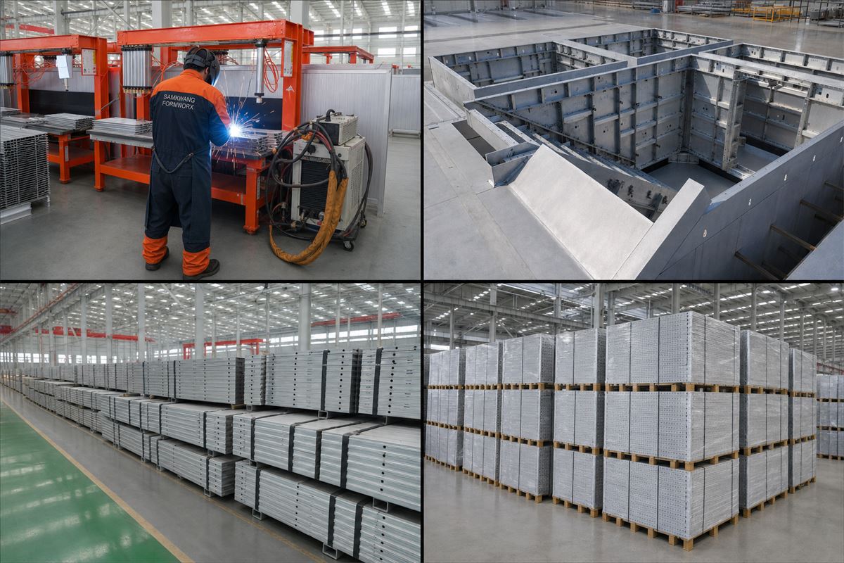
Our supervisor runs the first assembly cycles with your crew and hands the layout logic over to site staff.
Panels are packed by unit and block to the drawings, arriving straight at their installation zone.
5 days shell drawing review · 2 weeks non-standard lead time · 100% mock-up verified · 20 non-standard shape types.
Six controlled steps take A6061-T6 extrusions to numbered, packed form sets — with dimensional checks at every process handover. Quality is decided in the factory.
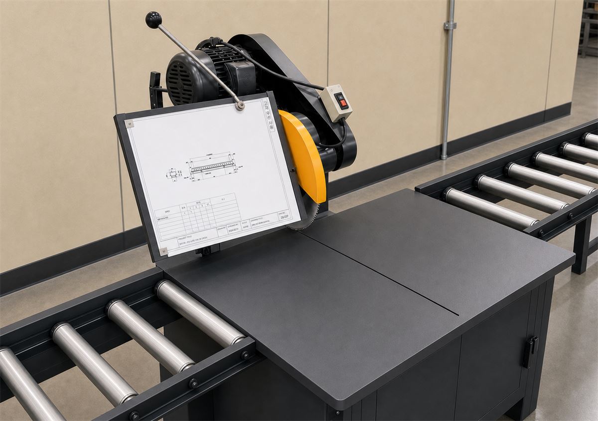 01CuttingAluminium profiles cut to precise length.
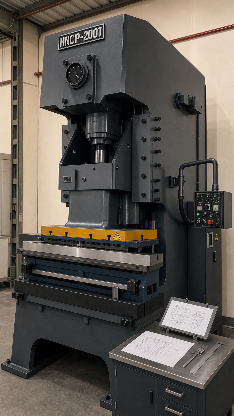 02MachiningParts formed by hole machining and punching.
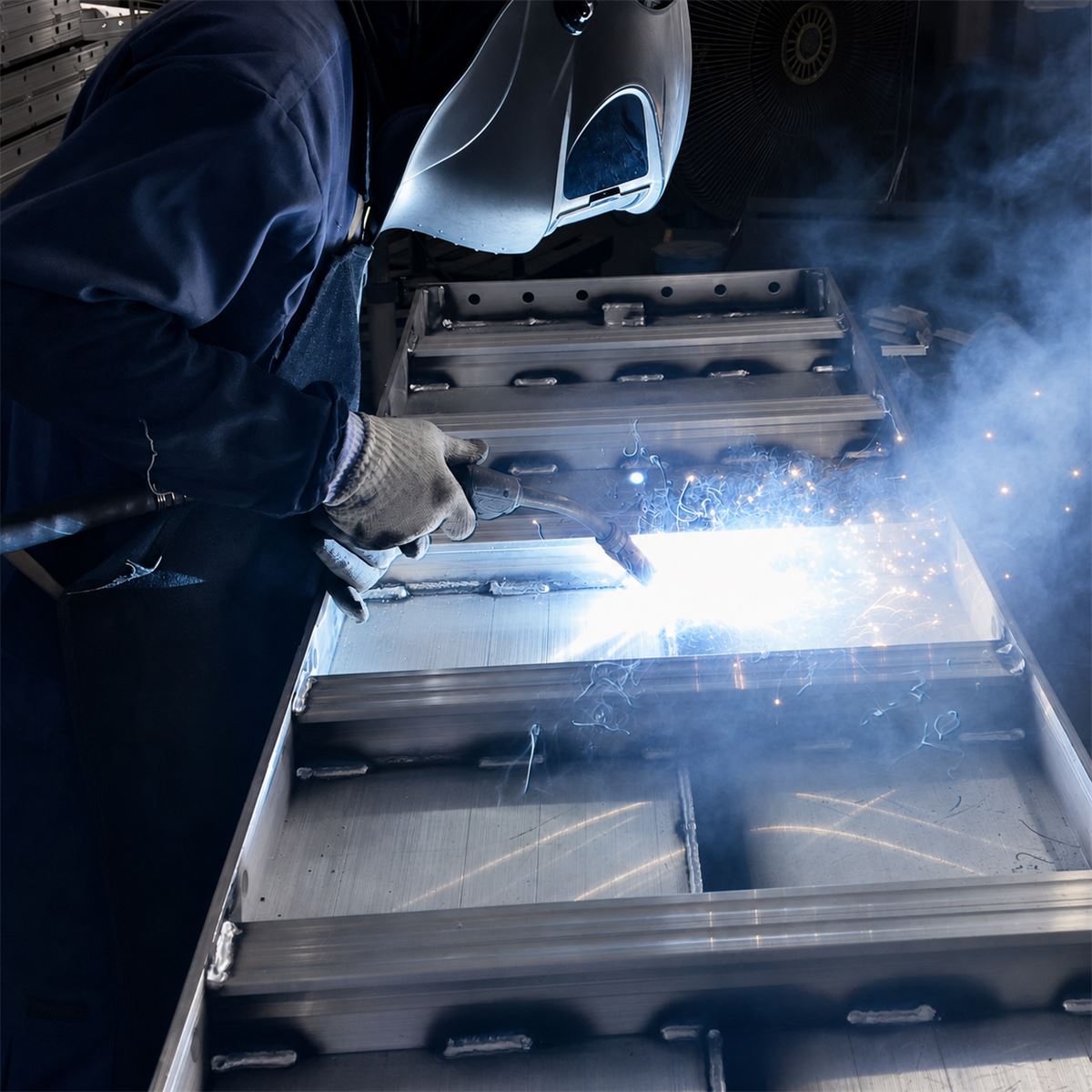 03WeldingParts welded and assembled.
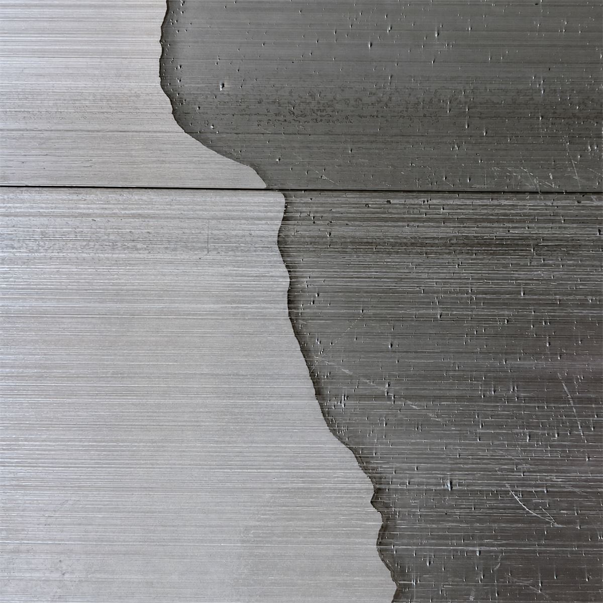 04Finishing & coatingSurface ground, then powder-coated.
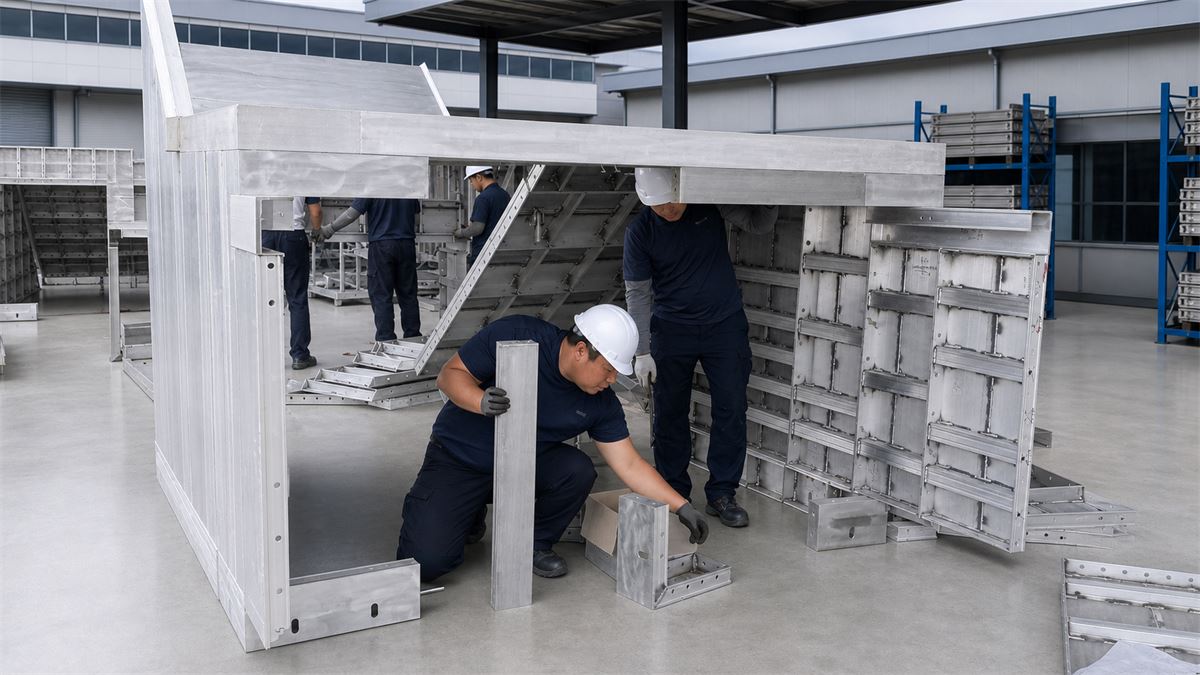 05Mock-upDimensions and quality checked through mock-up.
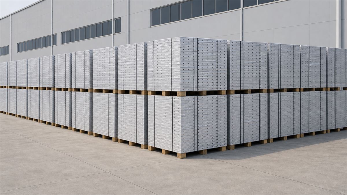 06Inspection & packingQuantities verified, then packed and shipped.
The same weld path on every panel — no operator variance.
Friction-stir joining adds almost no heat, so face sheets stay flat.
Continuous weld beads withstand repeated lateral pressure.
Inspection points Dimensional check after cutting & punching flatness check after welding trial assembly before packing
Send your structural drawings — shell drawings come back for review in 5 days, from the location nearest your project.